The Jaguar XJ40 ride levelling system (SLS) [page 2]


January 2017
The Jaguar XJ40 ride levelling system (SLS) on a 1993 XJ40: introduction and operation
– Components of the XJ40 SLS system on a 1993 V12 (this page)
– Typical failures of the ride levelling system
The components of the XJ40 SLS system
25 January 2017
This text is published preliminary and will be elaborated later on. Furthermore, no page is linked to it. Now just some pictures and a little explanation …
Ride levelling was standard on most XJ40s, in particular on the more expensive models like the Daimlers. Only in the last year of production of the XJ40, 1994, the ride or self levelling system (SLS) was not standard or even not available because it proved so problematic (have to figure that out).
Many of the XJ40s equipped with the ride levelling system were converted to standard rear suspension with standard shocks later on, after a component of the SLS had failed. Although Jaguar adviced to remove almost all components of the SLS, this is not necessary and many cars still have several components of the SLS system on the car after the system itself was made unoperational. I will show of which components the SLS system typically consists of. My Daimler Double Six is the subject: when I bought it, it had SLS, but soon afterwards it was deleted, although many components stayed on the car.
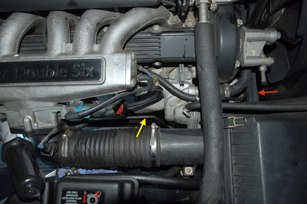
The first and most easy to spot part of the SLS system, is the reservoir for the special Jaguar Hydraulic System Mineral Oil (HSMO) for the SLS system. This was introduced in 1993 (the system saw many changes during the lifetime of the XJ40, which I will explain in a later article). It is the reservoir with the green cap, next to the steering oil reservoir, as seen below on my DD6. The lower hose supplies hydraulic oil to the high pressure pump, the upper hose receives the oil from the valve block. If the reservoir with the green cap is not present, then of course there cannot be a ride levelling system on a 1993 or 1994 XJ40.

On the above photograph, also two metal lines are arrowed. The line with the red arrow is for the front wheel brake. The line with the yellow arrow is for the hydraulic levelling system. This line runs along the bulkhead from the right hand side to the left hand side of the car (as seen from the driver's position, as always). At the V12 it can be seen clearly. Then it runs down to dive under the car.
On the photo below, the line again is indicated with a yellow arrow. The location of the tandem pump is indicated with the red arrow.
The line feeds high pressure hydraulic oil to the rear wheel struts. So it is logical that it comes from the valve block.
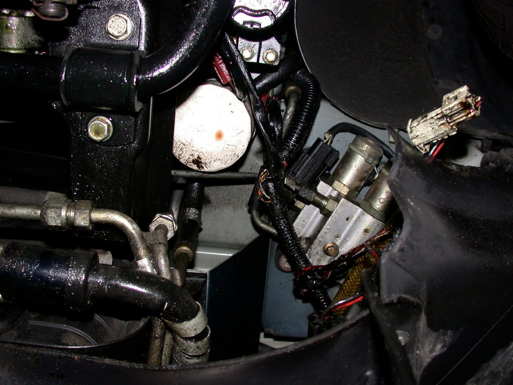
The hydraulic valve block contains two or three valves, operated with electric solenoids, to let the oil under very high pressure (up to 150 bar!) go to the rear wheel struts or release it. As of model year 1993 the valve block is placed behind the screen wash reservoir and over the front wheel brake air ducts. In particular at the V12, it is impossible to see it without taking things apart. Below the block was photographed by me when the SLS system was made unoperational and several parts have been removed to get at it. We look from under the car. At the left top of the photo we see the anti-roll bar with its bracket and bush, then to the middle we see the white steering oil filter canister. The radiator with several cooling pipes is on the lower left. The valve block is in the middle right of the photo. We see two solenoid cylinders and the rear wheel feed line coming from above going into the valve block at the lower end.
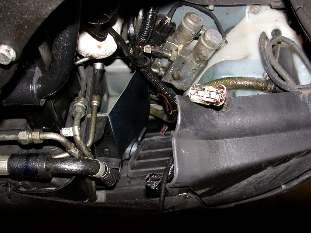
To give a better idea of its position, the photo below was taken to the front of the car. We see the valve block, the screen wash reservoir and below the underbelly panel/spoiler. The black piece with the two louvres in the lower middle is the intake for the brake air duct, which is removed to get at the valve block.
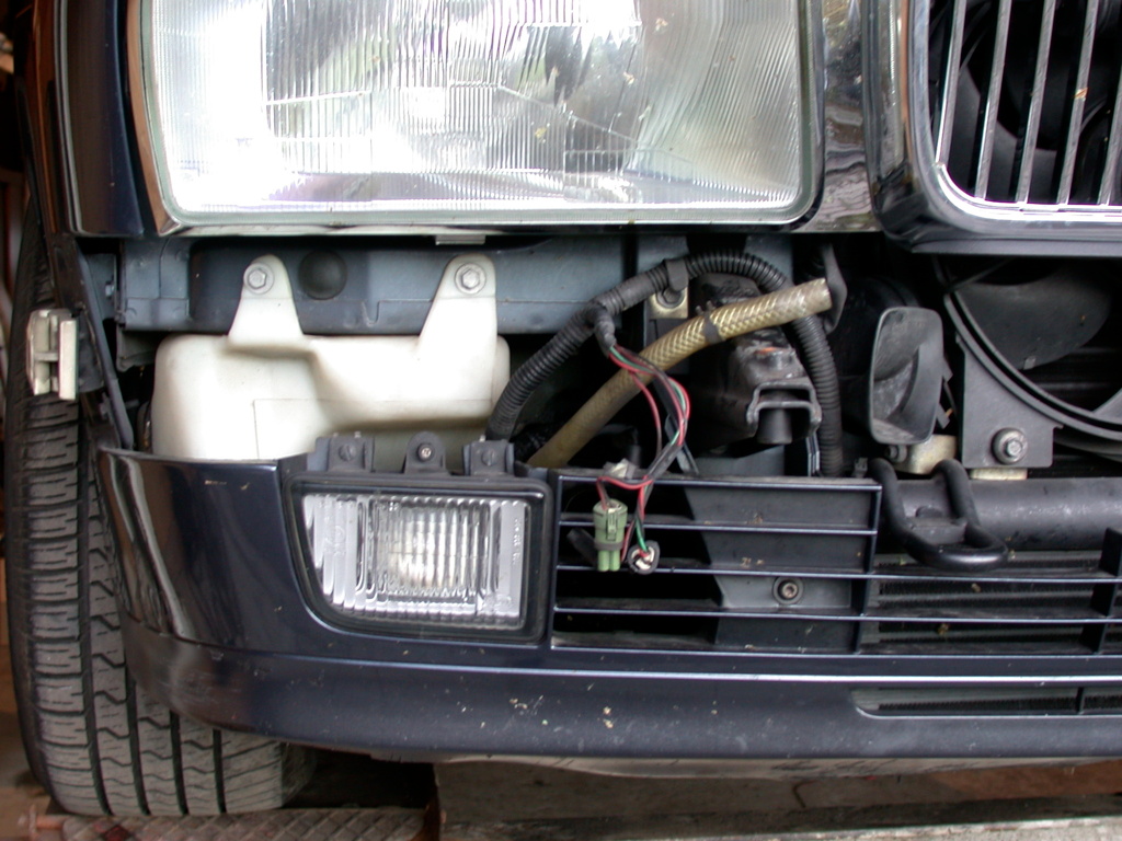
As a reference a picture of the same car with the bumper removed. The brake air duct intake with the two (apparently three) louvres and the screen wash reservoir are visible.
The hydraulic pump supplies very high pressure hydraulic oil to the valve block. The pump for the XJ40 V12 (XJ81) is unique: it is a tandem pump, that is two pumps on one shaft. The front part of the device is the hydraulic pump (a three? cylinder piston pump) and the rear is the power steering pump (a vane pump, probably because the required pressure is not as insanely high as for the ride levelling). The two pumps are on the same shaft, but furthermore have nothing in common: not the oil feed and not the pump itself.
Here the tandem pump can be seen in front. If the SLS is removed from the car, it is not necessary to replace the tandem pump for a sole steering pump. Apparently Jaguar advices to plug the lines, but probably the pump can also keep turning with the lines still connected but without oil? Comments welcome. In my case, as the tandem pump was reported to leak (I did not check that), the tandem pump was replaced by the steering pump only, on the rear of the photo. Just like the tandem pump, this device is for the V12 only.

Now the layout of the lines and the tandem pump. In the next photo, the white arrow points at the bracket for the air filter box, which has to be removed clearly. The tandem pump is in the upper middle of the photo.
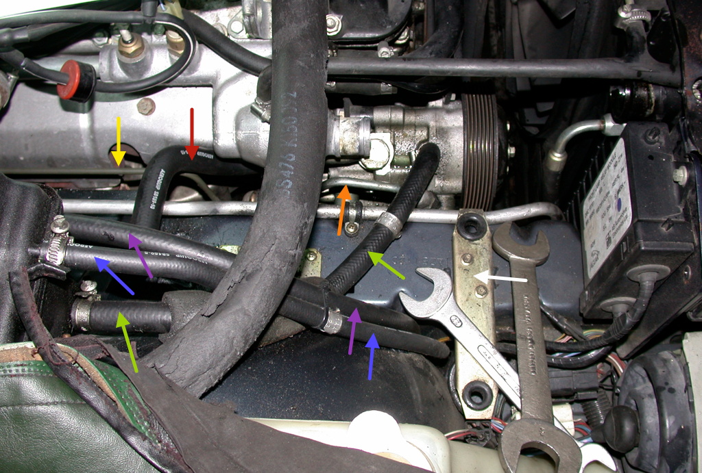
The line to the rear struts we saw in earlier photos is also arrowed yellow in this photo. It comes from the left and dives to the valve block, which is under the chassis and not visible in the photo. The oranje arrow points at the high pressure line that feeds oil from the pump to the valve block. As said the front part of the tandem pump is for the ride levelling. It gets his oil from the reservoir via the rubber hose with the two green arrows. The excess oil from the valve block is fed back to the reservoir via the rubber hose with the two blue arrows. Normally the lower hose of a reservoir is the feed and the upper hose is the return, logically. Both can be seen at the extreme left of the photo: the two hose clamps indicate them.
The two other rubber hoses are for the steering oil. The thick rubber hose with the red arrow feeds the steering oil from the reservoir to the back of the tandem pump, where the steering pump is. After the steering oil has done its job, it is fed through the white oil filter one the photos above and comes back through the hose with the pink arrows to the steering oil reservoir. To be complete.
So, as you can see it is a lot of work to work on the SLS of the XJ81 V12, as many parts have to be removed and even then it is difficult to get at the pump, for example.
The rear of the car
Let's now move on to the rear of the car.
As of model year 1993, all lines under the car (five in total) are on the left hand side of the car. Before 1993, the SLS line was on the right hand side of the car. On the photo below, of my 1993 Daimler Double Six, we look under the left hand side of the car in the driving direction. If we count the lines from one to five, starting at the outside of the car or the left we see the following. From the fuel filter it is clear that line number 3 is the fuel feed to the engine. Line number 1, at the left, is the fuel evaporation line, going to the carbon canister. Line number 2 is the fuel return from engine to fuel tank. Line number 4 is the brake line, with the T-piece dividing into left and right brakes. Line number 5 is the hydraulic ride levelling system line.

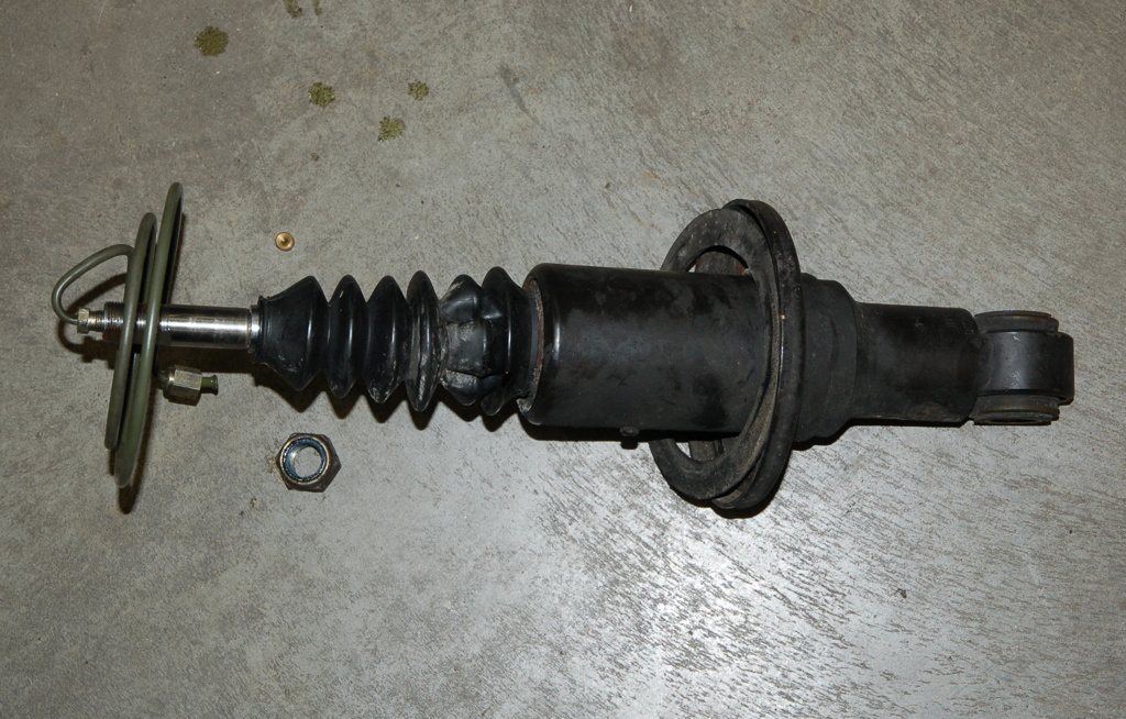
The SLS hydraulic oil line is going to the top of the left hand strut. In the upper spring pan is a T-piece. This copper coloured piece can be seen in the photo below, imaging the two SLS struts after removal from my Daimler Double Six. The 'McPherson-nature' of the struts is clear. The hydraulic oil is green. The oil is fed to the strut from exactly above, via the spiral line. This can also be seen in the second image below, on which I attached the oil line to the removed strut.

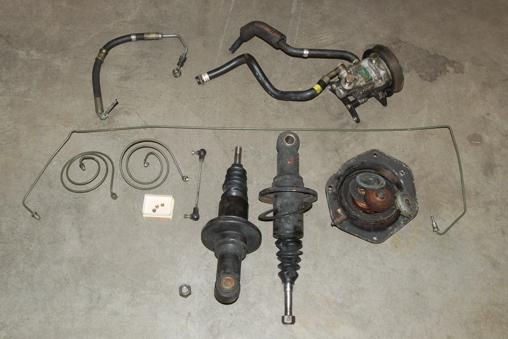
From the T-piece in the upper spring pan of the left hand side strut, an oil line is going to the right hand side of the car, where there is alto a T-piece mounted in the upper spring pan. In the image below I have collected all parts removed from my car with the removal of the SLS system. We see the long line feeding oil from the left to the right hand strut. Both struts are also visible, with the upper spring pans disassembled. On of the T-pieces is visible there. Furthermore, both spiral oil lines are visible, feeding the oil into the upper side of the strut shaft. The small things in the white matchbox are 'olives' which seal the connection of the spiral line to the strut.
We also see the tandem pump. The hose at the upper left is the high pressure steering oil hose, specifically belonging to this tandem pump and superfluous with the new steering-only pump. The springs were obviously left out of the photo. The link between the ride level sensor and the lower wishbone is also on the photo.
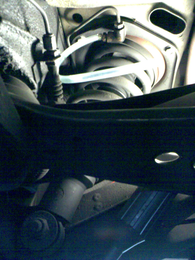
One side of the T-piece is connected to the spiral oil feed to the strut itself, the other side is plugged and is used to bleed the SLS system, as is visible on the photo below, the only one I have from this process (back in 2008 with a simple phone).
Of the sensing of the ride height I have only bad photos. It should look like the image below, taken from one the Jaguar documents.
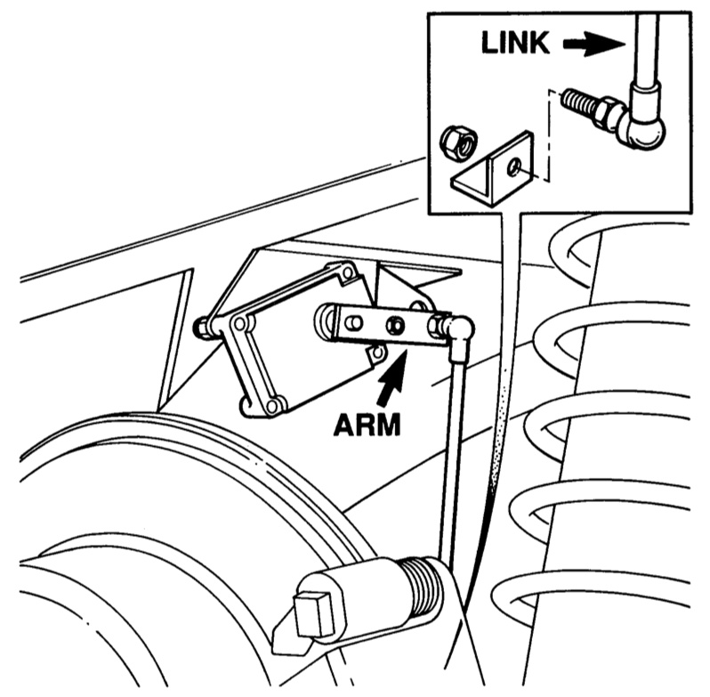
Of my Double Six, I only have this photo. With the right rear wheel removed, photographing it would have been a lot easier.
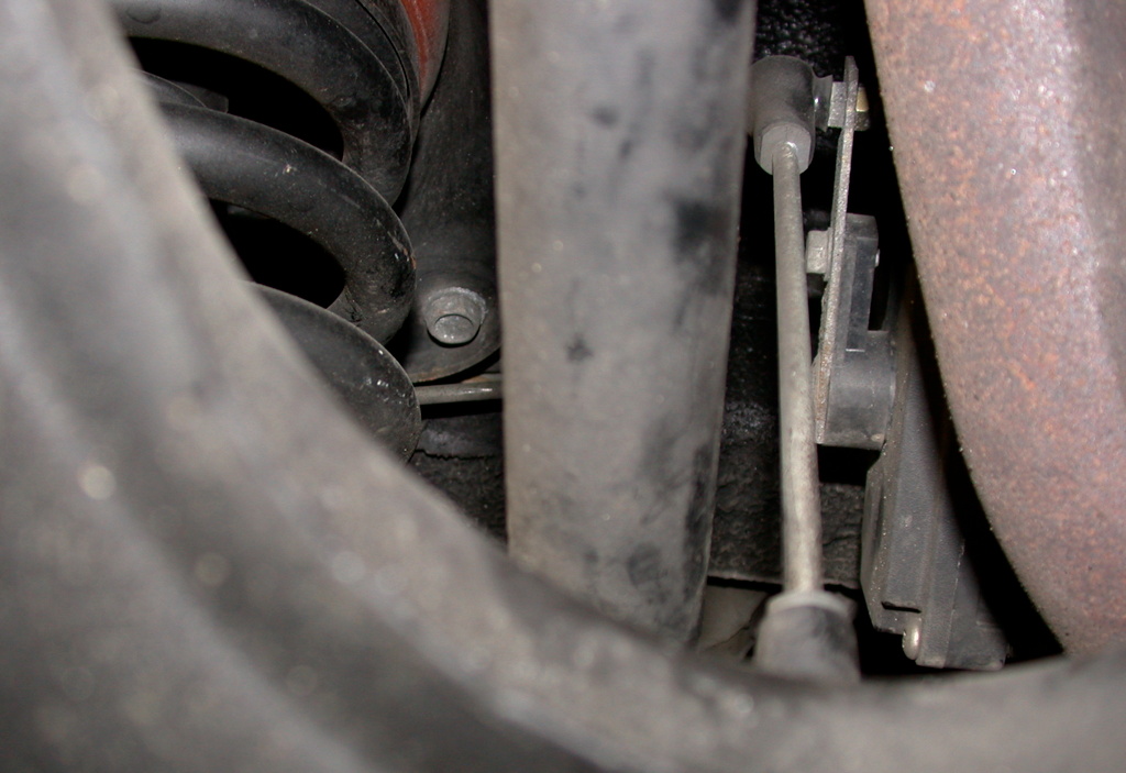
With the suppression of the SLS from the car, the link between the wishbone and the ride level sensor is removed. But the ride level sensor can be left in place, as here on a photo of my 1992 Regency Daimler six cylinder. We see the rear side of the sensor, with the electric lead removed. Normally the contact pins should be sealed with silicone or something like that.

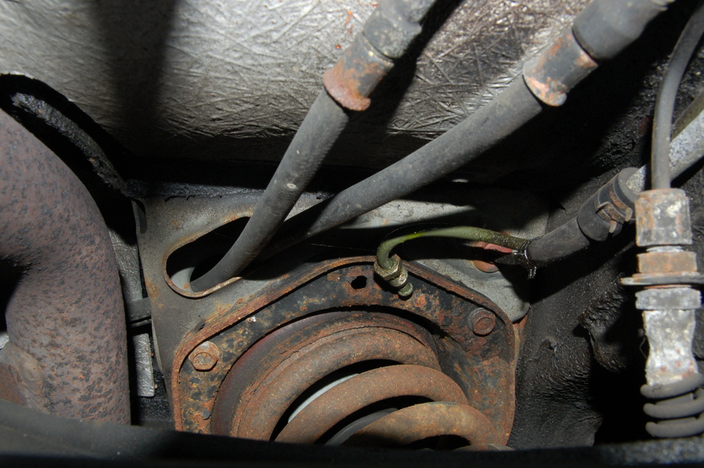
With the removal of the oil line between the left and right hand strut and the use of a conventional shock absorber assembly, it looks like this. On my car the SLS oil feed running under the car from the valve block to the rear strut was not removed. Next to it, we see the two fuel lines going to the bottom of the fuel tank.
Previous page: introduction on the ride levelling system (SLS) on a 1993 XJ40
Next page: failures of the ride levelling system (SLS)
Kind regards,
Rens Swart